IN 1904 the National Electric Signalling Company decided to erect two stations for trans-Atlantic working, the antennæ to consist of cylindrical steel tubes, 400 ft. high, with the National Electric Signalling Company's patent umbrella capacity at the top, each tube to rest at the bottom on a pivoted insulated base, and to be supported by sectionally insulated wire-rope guys of the company's standard type. This type of antennæ, which was invented and designed by the National Electric Signalling Company, and patented by it, has proved quite successful, and has been copied in Germany at the Nauen wireless station, a lattice-work, however, being used instead of a steel cylinder.
The sites selected were Brant Rock, 30 miles south of Boston, Massachusetts, U.S.A., and Machrihanish, on the far side of the Mull of Cantyre from Campbelltown, Scotland. These two points were selected because the great circle joining them passes up the Bay of Fundy, over the Isthmus of Chignecto, and across Newfoundland at a point where it is comparatively low. The contract for the steelwork and erection of these towers was let to the Brown Hoisting Machinery Company, of Cleveland, Ohio, U.S.A., and for the insulators to the Locke Insulator Company, of Victor, N.Y., U.S.A. Owing to delays on the part of the contractors, the towers were not completed until December 28, 1905.
On Friday, December 29, 1905, Brant Rock sent to Machrihanish, but nothing was received, owing, as it was afterwards learned, to a miscalculation in the wave-length. On January 2, 1906, Brant Rock sent again, and Machrihanish received the messages. Communication was maintained one way until about the middle of January, when, the sending apparatus at Machrihanish having been completed, Machrihanish sent, and Brant Rock received messages from there at the first trial. Very satisfactory communication was then maintained for some time, and code Messages containing as many as forty cipher words were received without a single error, or the necessity of any repetitions.
It was found that the amount of atmospheric absorption had been miscalculated. From tests made on shipboard at distances of 1500 miles, the atmospheric absorption had been found to be about 90 per cent.--i.e., 10 per cent. of the radiation got through. It was considered that, by assuming the atmospheric absorption to be 99 per cent.--i.e., that 1 per cent. of the radiation got through--a sufficient factor of safety would be provided. As the design was conservative, it was found that in practice the factor of safety was larger than this, and equivalent to an absorption of 99.8 per cent.--i.e., that messages could be received although only one-fifth of per cent. got through. Over this distance of 3000 miles, partly over land, it was found that the absorption was considerably greater than this, and that as a matter of fact, during daylight, not more than one-tenth of 1 per cent. of the energy got through, and that a factor of safety of at least 100,000 must be provided.
As an illustration, with the same sending power, on some nights messages were received 480 times stronger than was necessary for audibility, and the messages could be read with the receiver 6 in. away from the ear. On other nights with the same sending power the messages were so faint that they could not be read. A number of tests were made, which were witnessed by scientific experts from the General Electric Company in America, and Mr. Shields, the technical expert of Messrs. Abel and Imray, and others; but as it was evident that the stations were not sufficiently powerful for commercial work, they were shut down early in 1906, for reconstruction.
Owing to the impossibility of getting aluminium for the compressed-air condensers the stations were not opened again until October, 1906, when they were operated at a factor of safety of 2000, only half of the condensers being in place. With the full amount of condensers the factor of safety would have been 4000, and a new form of receiving apparatus, which it was intended to use, would have brought up the factor of safety to 400,000. The stations operated continuously, barring shut-downs for a couple of nights for mechanical reasons, until December 5, when the tower at Machrihanish blew down. This accident came at a very unfortunate time, as work had just been begun on a new method for eliminating the atmospheric absorption, which had given very promising results, the absorption having been already reduced to one-tenth of what it was formerly. Moreover, the new receiving apparatus had only been partly installed, and no opportunity had been afforded of trying it between the trans-Atlantic stations.
The specifications on which the contractors bid called for the tower to stand a wind-pressure of 50 lb. per square foot on a flat surface, and for the tower to be capable of being extended to a height of 500 ft. later, if desired, and to be capable of standing a pressure of 50 lb. per square foot on a flat surface even if one set of guys broke.
The design was carried out in a very creditable manner by the Brown Hoisting Machinery Company. In a future issue we shall illustrate the installation and describe the jointing of the guy-ropes, to the failure of which the fall of the mast is attributed. This jointing was carried out by a subcontractor.
Engineering, January 25, 1907, pages 108-111:
TRANS-ATLANTIC WIRELESS TELEGRAPHY.
IN our last issue we described the wireless telegraph stations constructed, one at Brant Rock, Massachusetts, U.S.A., and the other at Machrihanish, N.B., by the National Electric Signalling Company of America, for trans-Atlantic service. It will be remembered that shortly after all preliminary experiments had been made, and the apparatus got into proper working order, the tower at Machrihanish was blown down by a storm. The primary cause of the disaster was the faulty jointing of the guy-ropes; and, by the courtesy of the National Signalling Company, we are now able to describe more fully the construction of the towers, and to reproduce photographs illustrating the details primarily responsible for the fall of the tower.
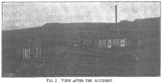
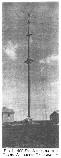
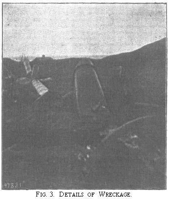
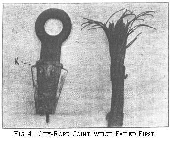
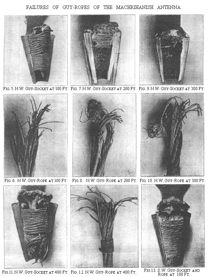
Fig. 1, page 108, is a photograph the tower at Brant Rock, the one at Machrihanish being identical with it in every respect. Figs. 2 and 3 show the appearance of the wreckage of the Scotch tower after the accident, and Fig. 4 shows a view of a socket and cable end wrenched apart, the socket having been sawn in two to render the joint visible. Further views of the same socket and rope are given in Figs. 11 and 12, page 109, and are of special interest, as this was the joint which failed first. Figs. 5 to 10, and Fig. 13, on the same page, show the condition of other joints which failed, the guys to which they belonged being indicated underneath the respective illustrations. Figs. 5 and 6 show a joint which belonged to the 100-ft. guy rope on the north-west side. In Fig. 7 another socket is shown, and the corresponding rope, of which several strands were torn, as illustrated Fig. 8. Fig. 9 shows a socket as discovered, one half being cut away to show the interior. The rope end belonging to it is shown in Fig. 10. All the strands are practically intact, and the rope has apparently been able to come out without much injury to itself, on account of the bad pouring of the zinc. Fig. 13 shows the rope and socket of the 100-ft. guy on the south-west side. The joint never completely separated, but the rope slipped ½ in. in the socket, proving the faultiness of the method of attachment.
The following are the calculated stresses given by the Brown Hoisting Machinery Company for the different sets of guys, at 50 lb. pressure on a flat surface:
Lb.
Top guy
... ...
18,400
Second guy
... ...
14,750
Third guy
... ...
13,200
Fourth guy
... ...
12,800
Tests made at the Massachusetts Institute of Technology, by Professor Miller, to determine the breaking strength of the insulator, showed that the insulators were stronger than the forgings to which the wire ropes and insulators were attached, the holes in the steel forgings elongation ¼ in. at 46,000 lb.
A new method of attachment was used, and it was found that the porcelain insulators cracked between 51,000 lb. and 50,000 lb. The tower is insulated to stand approximately 500,000 volts. When the potential reaches above 500,000, discharges take place over safety-gaps, to prevent injury to the insulators.
As regards the method of fastening the wire ropes to the steel forgings, it had been intended to use Crosby clamps. The engineers of the Brown Hoisting Machinery Company, however, pointed out that the method used by Roebling had proved very satisfactory in the case of the Brooklyn Bridge, and this method was adopted. This method is shown in Fig. 14, annexed. A piece of binding wire A is put around the cable, and each strand of the end of the cable unlayed, so that no two wires are twisted together. The unstranded end of the cable, which is, of course, of galvanised wire, is then dipped in dilute hydrochloric acid. The wires are then bunched together and pushed into the socket C. A wire is wrapped around the cable at B, as shown.
The socket C is then poured full of zinc D, as shown. The socket is then washed with water. It might be thought that there would be some corrosion from the hydrochloric acid, but a careful examination made a few weeks ago of the sockets which had been poured nearly two years ago showed that absolutely no corrosion had taken place. The strength of this joint is shown by Professor Miller's tests at the Massachusetts Institute of Technology, where the steel forgings (castings?) went at 46,000 lb., and the insulators at 56,000 lb., without the rope pulling out. In addition, the joints, which were made on the Brooklyn Bridge by this method, continue, so we are informed, to be entirely satisfactory. As regards strength and durability, therefore, experience appears to show that this form of joint leaves nothing to be desired, provided, of course, it is properly made. As soon as the accident to the tower at Machrihanish was reported, the National Electric Signalling Company cabled for information as to the cause, and found that the accident had been due to the cables pulling out of the sockets. Further investigation showed that the Brown Hoisting Machinery Company had adopted a method of making these joints differing from that above described. This method is shown in. Figs. 15, 16, and 17, above. In Fig 15 the end of the cable is shown stranded. In Fig. 16 a portion of the end is turned back. In Fig. 17 a wedge F is driven into the stranded end of the cable, and melted zinc is poured into the space G.
It will be evident that with this form of joint the principal dependence is upon the friction between the wire and the wedge and the socket. The fact that this form of joint is very much inferior to the Roebling joint used at Brant Rock is shown by the fact that after the fall of the Machrihanish tower it was found that five or six of the joints had been pulled out, showing the joint had given way first, before either the insulator, or the socket, instead of, as with the Roebling joint used at Brant Rock, the socket and insulators giving way first. Even with this inferior type of joint, the tower would doubtless have withstood the wind pressure but for the way in which the joints were made by the man employed for the purpose by the sub-contractors to whom the work was entrusted by the Brown Hoisting Machinery Company. The joint which gave way, and caused the destruction of the tower, is shown in diagram in Fig. 18, and Figs. 4, 11, and 12, already referred to, show the final appearance of the first joint to fail.
The wedge H split, and, as will be seen from the illustrations, the fact that the wedge was split was plainly visible--it was simply pounded flat. The wedge then, instead of being withdrawn and a new wedge inserted, as should have been done, prevented the melted zinc from flowing into the socket; and as in addition the zinc was cold, the rope was merely held in the socket by the friction between the rope and the socket. The only wonder is that the tower did not fall before. It will be seen, therefore, that the fall of the tower was due to the joint being left in the condition indicated by the photograph. Fortunately, it happened that no lives were lost through the fall of the tower. Quite apart from the question of workmanship, the form of joint used appears to be much inferior to the Roebling type, and if the latter had been used, the tower would probably still standing, as it was designed so as to stand the necessary wind-pressure even with one side of guys entirely gone. The fact that all the joints pulled out, instead of pulling the sockets apart, shows conclusively that the joint is not what it should be. In addition, care should be taken, whether the Roebling or other type of joint be used, to ensure that the zinc is poured in a sufficiently hot state. We are informed that examination showed that a considerable number of joints made by the workman above referred to had been poured too cold.
Diagrams showing the method of staying of the tower, and the stages in its fall, are given in Figs. 19 to 24 on page 110. After one stay had gone, the top of the tower leaned over under the tension of the opposite stay, and threw more stress on the remaining cables. They parted one by one, until the tower collapsed at about a quarter of its height from the ground, as shown in Figs. 21, 22, and 23. The plan of the wreckage is shown in Fig. 25, which is comparable with Figs. 2 and 3 previously given. The guy attached at the 400-ft. level went first, the 300-ft. guy succeeded it, and so on.
The above experience is published for the reason that wire-rope is being used in a great deal of engineering construction work; and there have from time to time been a considerable number of accidents caused by the pulling out of improperly-made joints.